Quick Answer
Industrial backup power planning starts with load priorities, motor starting demand, operating duration, redundancy, and site conditions.
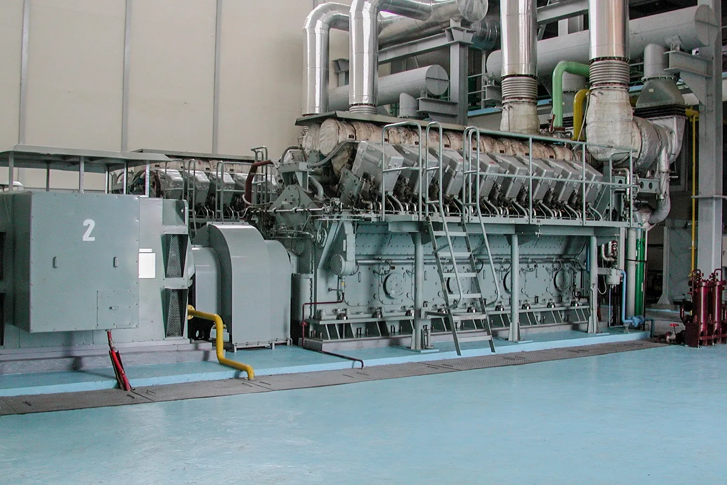
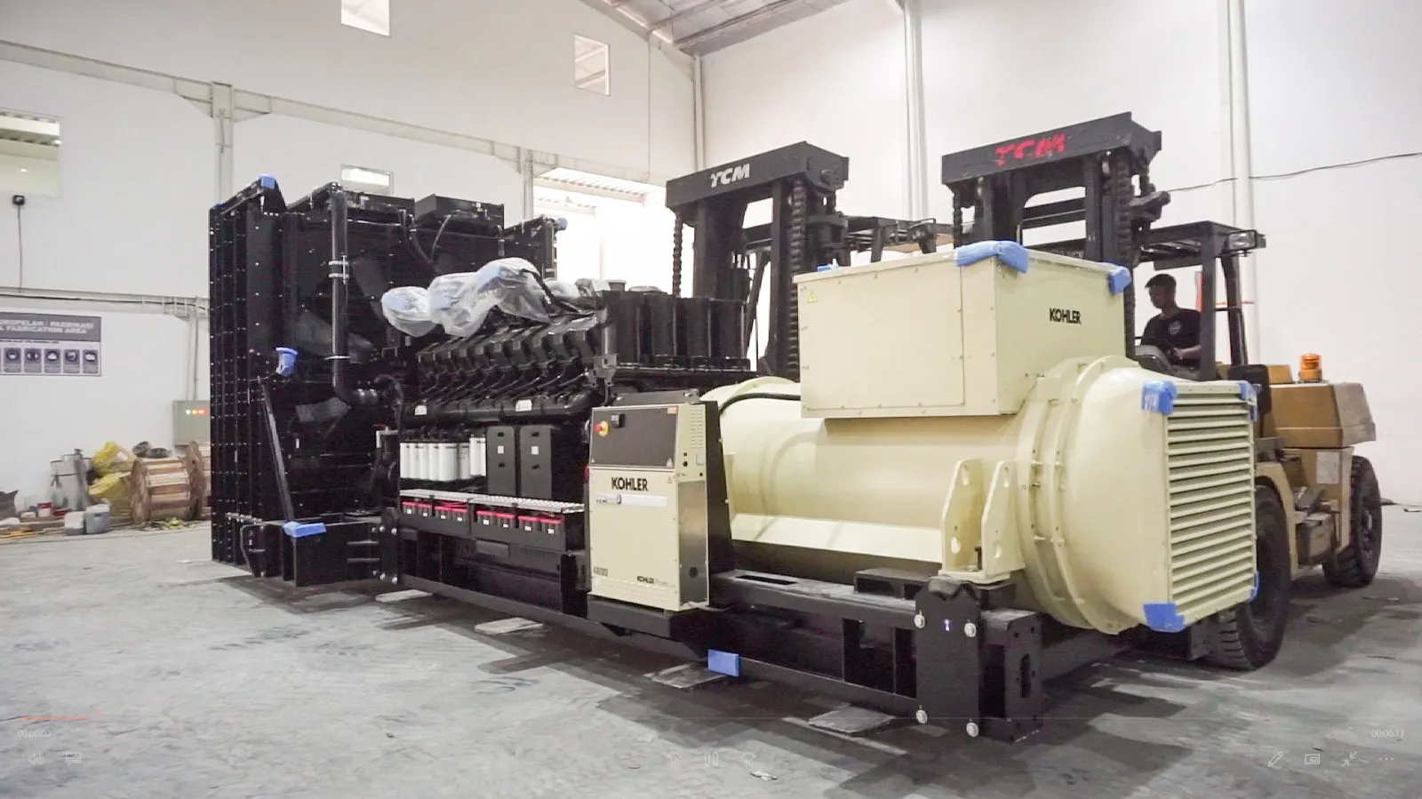
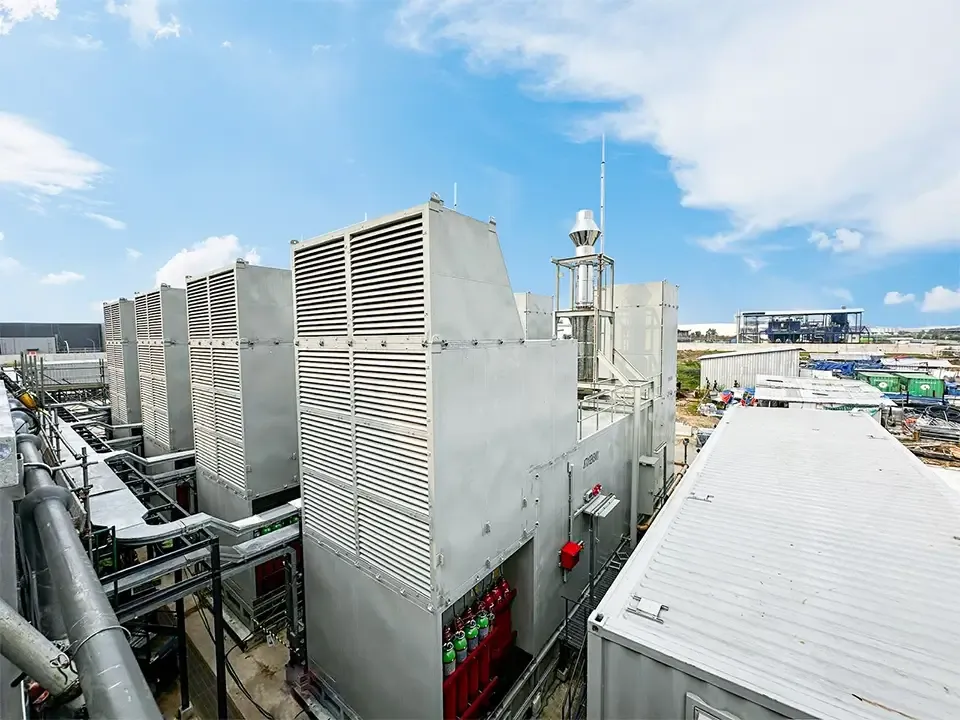
Industrial backup power planning requires more than adding the ratings of every machine in a facility. A useful calculation must reflect which equipment needs to continue operating, how loads start, how long backup power must remain available, and what happens if one component fails.
Therefore, the process begins with operational priorities rather than generator capacity. Once the team understands the loads and outage risks, it can develop a power requirement that supports the facility without creating unnecessary excess capacity.
Define What the Backup System Must Achieve
Before calculating power, the project team needs to define the purpose of the backup system. Some facilities only need enough power to shut down equipment safely. Others must continue production, maintain environmental conditions, or support critical services throughout an outage.
These objectives produce different power requirements. A controlled shutdown may only require control systems, safety equipment, pumps, communications, and selected process loads. Continuous operation may require a much larger portion of the facility.
The team should also define the acceptable interruption time. Equipment that cannot tolerate a short break may need a UPS or another bridging source while the generator starts and reaches stable operation.
Finally, the facility needs a target operating duration. This target affects fuel storage, cooling, maintenance planning, staffing, and refueling arrangements.
Create a Complete Load Inventory
A reliable calculation starts with accurate equipment data. The team should collect information from electrical drawings, equipment nameplates, operating records, control-system data, and equipment suppliers.
The inventory should include more than the main production machines. Pumps, cooling equipment, ventilation, lighting, control panels, compressors, IT systems, fire-protection equipment, and auxiliary systems may also need backup power.
Useful data includes:
- Equipment description and operating function
- Rated power in kW or kVA
- Power factor
- Voltage and phase
- Running current
- Starting current or locked-rotor data
- Starting method
- Operating sequence
- Duty cycle
- Criticality level
- Existing power source
- Expected future changes
The team should verify whether a motor nameplate shows mechanical output or electrical input. Using shaft output without considering efficiency can underestimate the electrical requirement.
Separate Critical and Noncritical Loads
Not every connected load needs generator power. Therefore, the project team should classify equipment according to operational impact.
Critical loads support safety, control, communications, environmental conditions, or processes that cannot stop abruptly. Essential loads help the facility continue limited operations. Meanwhile, noncritical loads can remain off until utility power returns.
This classification helps prevent oversizing. For example, a facility may not need to operate every production line, comfort-cooling unit, office appliance, and workshop load during an outage.
However, load classification requires input from operations, maintenance, safety, IT, and management. Electrical data alone cannot determine which processes the facility must protect.
Build a Load-Priority Matrix
A load-priority matrix connects electrical demand with operational consequences. It can show which equipment must start first, which equipment can wait, and which equipment should remain disconnected.
The matrix should also identify dependencies. A production machine may require a lubrication pump, cooling system, control panel, and material-handling equipment before it can operate safely.
By mapping these relationships, the team can avoid restoring a main load before its supporting systems become available.
Calculate the Running Power Requirement
After classifying the loads, calculate the power that each operating scenario requires. The team should distinguish real power in kilowatts from apparent power in kilovolt-amperes.
A basic relationship is:
Apparent power (kVA) = Real power (kW) ÷ Power factor
For example, equipment with a lower power factor requires more apparent power for the same amount of real power. Therefore, the generator and alternator must support both values.
However, simply adding nameplate ratings can overstate or understate the actual demand. Some equipment rarely operates at full output, while other loads run simultaneously during peak production.
Operating records, metering data, and discussions with facility teams can help establish realistic demand. Nevertheless, historical demand alone may not show the conditions that occur during restart after a power failure.
Account for Simultaneous Operation
The total connected load represents all equipment that could operate, but the peak simultaneous load reflects what actually runs at the same time.
A facility may have several pumps with one standby unit, multiple compressors that cycle according to demand, or production lines that operate in different shifts. As a result, the generator may not need to support every nameplate rating at once.
The team should create several operating scenarios, such as:
- Normal production during an outage
- Minimum safe operating condition
- Peak production demand
- Equipment restart after a power interruption
- Maintenance operation with one system unavailable
- Future operating condition after expansion
Scenario-based calculations provide more useful information than a single total. They also reveal which condition creates the highest running demand or largest sudden load step.
Evaluate Motor Starting Demand
Motors can draw much more current during startup than during normal operation. Pumps, compressors, conveyors, chillers, crushers, and production machines may therefore determine the generator requirement even when their running demand appears moderate.
The starting method affects the size of the electrical step. Direct-on-line starting creates a different demand from star-delta starting, a soft starter, or a variable frequency drive.
Mechanical conditions also matter. A motor that starts under load may require a different response from one that starts without load.
If several motors start simultaneously, the generator may experience a significant voltage or frequency drop. Consequently, controls may reset, contactors may release, or other motors may stall.
Calculate the Largest Load Step
The project team should identify the largest load that can connect at one time. It should then evaluate the generator’s transient response, not only its steady-state capacity.
Load sequencing can reduce the largest step. For example, the control system can start a lubrication pump first, followed by a cooling fan, compressor, and main process equipment.
This approach may reduce the required generator capacity while preserving reliable operation. However, the sequence must match the actual process and control logic.
Review UPS and Electronic Loads
Industrial facilities increasingly use UPS systems, variable frequency drives, rectifiers, automation equipment, and electronic power supplies. These loads can introduce harmonics and create operating characteristics that differ from conventional motors or resistive equipment.
UPS systems require particular attention. During an outage, the UPS may support sensitive equipment from its batteries while the generator starts. After transfer, it may supply the connected load and recharge the batteries at the same time.
Consequently, the generator may see more than the downstream IT or control load. The calculation should also consider the UPS input characteristics, recharge settings, efficiency, and operating mode.
The project team should coordinate generator, alternator, UPS, controller, and protection requirements. In some cases, an alternator or control adjustment can address the load characteristics more effectively than a larger engine.
Arrange Loads into Recovery Stages
A generator should not necessarily receive every critical load at once. Instead, the facility can divide equipment into recovery stages.
The first stage may include protection, controls, communications, emergency systems, and essential pumps. The next stages can restore cooling, process equipment, production machines, and less critical services.
A delay between stages gives the generator time to recover its voltage and frequency. In addition, the control system can stop the sequence if available capacity falls below the required margin.
The team should document each stage, its estimated demand, starting characteristics, and dependencies. This information supports controller programming and commissioning.
Consider Ambient Conditions and Site Derating
Generator output depends on the installation environment. High ambient temperature, elevation, restricted airflow, and radiator discharge recirculation can reduce the power that the system can deliver.
Therefore, the project team should provide accurate site data to the supplier. Indoor installations require sufficient combustion air and heat rejection, while outdoor installations need protection against weather, drainage problems, and environmental exposure.
Exhaust-system restrictions can also affect engine performance. Long pipe runs, multiple bends, unsuitable silencers, or small pipe dimensions may create excessive backpressure.
A generator that appears adequate under standard conditions may not provide the same output at the actual site. The calculation must therefore connect electrical sizing with mechanical and environmental design.
Select the Correct Operating Rating
Generator ratings describe how the unit handles load and operating duration. Standby, prime, and continuous applications follow different operating profiles and manufacturer conditions.
A facility that uses the generator only during utility failures has a different duty from a remote site that relies on generator power every day. Likewise, a generator that operates in parallel with another source requires a different review from an isolated standby unit.
The team should define expected operating hours, load variation, outage frequency, and maintenance conditions. It can then compare generator proposals on an equivalent rating basis.
Capacity alone does not provide enough information. Two units with similar kVA values may follow different operating limitations.
Determine the Required Redundancy
A single generator may support facilities that can tolerate downtime during maintenance or repair. However, critical operations may require more than one unit.
An N configuration provides enough capacity for the planned load. Meanwhile, an N+1 arrangement adds a unit or capacity margin so the system can continue operating if one unit becomes unavailable.
Multiple generators can also provide flexible capacity. The control system can start additional units as demand rises and stop them when demand falls.
However, parallel systems require synchronizing switchgear, load-sharing controls, communication, protection, and more complex commissioning. Therefore, the redundancy decision should follow operational risk rather than a default preference.
Include Future Growth Carefully
Industrial facilities often plan new machinery, production lines, cooling systems, or building extensions. The backup-power calculation should account for credible expansion.
However, a large arbitrary margin can increase equipment, switchgear, fuel-system, and installation costs. It may also cause generators to operate at low loads too frequently.
Instead, the team should identify specific expansion stages and estimate their loads. If the timing remains uncertain, a modular system may allow the company to add capacity later.
This approach supports growth while keeping the initial system proportional to present requirements.
Calculate the Fuel and Runtime Requirement
Electrical capacity answers how much power the facility needs. Runtime planning determines how long the system can provide it.
The team should estimate fuel use from the expected operating load rather than relying only on maximum generator capacity. It should then consider the required autonomy, refueling access, delivery reliability, and storage limitations.
Longer runtime may require a base tank, day tank, main storage tank, transfer pumps, piping, filtration, level monitoring, and safety controls.
Fuel quality also matters. Water, sediment, and microbial contamination can affect the injection system. Therefore, the operating plan should include fuel inspection and storage management.
Check Switchgear and Distribution Capacity
The generator must work with the facility’s electrical distribution system. Cables, circuit breakers, busbars, transformers, ATS panels, and protection devices must support the expected current and fault conditions.
The control philosophy should define startup, transfer, load sequencing, load shedding, synchronization, shutdown, and return to utility power.
If available generator capacity falls, load shedding can remove lower-priority equipment and preserve critical operations. However, the team needs to define and test this logic before an actual outage.
Protection coordination also requires attention. The system should isolate faults without unnecessarily disconnecting healthy sections of the facility.
Develop a Calculation with Clear Assumptions
A useful sizing document should explain where every value comes from. It should identify measured data, nameplate data, operating assumptions, diversity, starting requirements, environmental conditions, and future allowances.
The document should also separate confirmed information from estimates. This distinction helps the team identify which data still requires verification.
A calculation may include:
- Connected load
- Critical running load
- Peak simultaneous demand
- Largest motor or load step
- UPS and nonlinear-load contribution
- Site derating
- Redundancy requirement
- Expansion allowance
- Required runtime
- Operating scenarios
Clear assumptions make the study easier to review. They also reduce disagreements when suppliers recommend different generator sizes.
Validate the Result with Technical Modelling
Manual calculations provide a strong starting point, but complex facilities may require generator-sizing software or manufacturer application tools. These tools can model transient voltage and frequency response more accurately.
The supplier should use verified engine, alternator, and controller data. Generic assumptions may not reflect the performance of the proposed configuration.
Nevertheless, software cannot correct inaccurate input. The project team still needs to provide reliable load data, starting methods, operating sequences, and site conditions.
Technical modelling should support engineering judgment rather than replace it.
Confirm the Design through Testing
Calculations establish the requirement, but commissioning confirms whether the complete system works. The test should cover the generator, fuel system, cooling, switchgear, controls, protection, and load sequence.
Technicians can apply load in stages while monitoring voltage, frequency, current, temperature, alarms, and recovery time. Motor-starting tests can also confirm transient performance.
A utility-failure simulation helps the team observe generator startup, ATS transfer, UPS response, load restoration, load shedding, and return to normal power.
If the system does not meet the expected performance, the team can adjust settings, change the load sequence, or review the design before final handover.
Avoid Common Calculation Mistakes
One common mistake involves using only the total connected load. This method ignores operating scenarios, motor starting, diversity, and load priorities.
Another mistake involves applying a large spare-capacity percentage without a defined expansion plan. Although the intention is to provide flexibility, excessive capacity can create unnecessary costs and operating challenges.
Teams may also overlook UPS recharge demand, site derating, auxiliary equipment, or the capacity of existing switchgear.
Finally, a spreadsheet alone cannot validate the complete system. The design must connect load calculations with controls, mechanical systems, installation conditions, and testing.
Build the Requirement around Real Operations
A practical backup-power calculation reflects how the facility actually operates. It considers critical loads, simultaneous demand, motor starting, electronic equipment, load stages, environmental conditions, redundancy, and future growth.
For industrial facilities, the selection of an industrial generator should follow the load study rather than precede it. This sequence helps the project team focus on operational requirements before comparing equipment.
PT Conductorjasa Suryapersada supports the planning and evaluation of backup power systems for industrial facilities. The process can begin with existing load data, electrical drawings, and operating priorities, then develop into a system configuration that matches the facility’s actual risk and power requirements.
Frequently Asked Questions
How do engineers calculate backup power requirements?
Engineers identify critical loads, calculate running demand, evaluate motor starting current, arrange load steps, apply site conditions, and include a justified allowance for future growth.
Should a generator support every connected load?
Not always. Facilities can separate critical, essential, and noncritical equipment, then connect loads according to operational priorities.
Why does motor starting affect generator capacity?
Motors can draw considerably more current during startup than during normal operation, which may cause voltage and frequency drops if the generator cannot support the load step.
How much spare generator capacity should a facility include?
No single percentage suits every facility. The project team should base spare capacity on defined expansion plans, operating risk, load uncertainty, and the selected redundancy strategy.